Page 3 of 6
Posted: Thu Oct 26, 2006 1:24 pm
by EURO
POLISH IT! nothing nicer then a nice shiny engine bay...
Posted: Thu Oct 26, 2006 1:32 pm
by Bennoz
Polished it is! I was already leaning that way....

Posted: Thu Oct 26, 2006 4:32 pm
by Supplanter
EURO wrote:POLISH IT! nothing nicer then a nice shiny engine bay...
It ought to add at least another 50kw at the wheels.
Posted: Thu Oct 26, 2006 4:35 pm
by Bennoz
Supplanter wrote:EURO wrote:POLISH IT! nothing nicer then a nice shiny engine bay...
It ought to add at least another 50kw at the wheels.
And thinking about it, polishing it will remove metal... less weight!
Posted: Thu Oct 26, 2006 5:15 pm
by mxysxy
Don’t polish!
Just get it in, so we get the results earlier!
I need more lowdown power to copy a project from!
When will be the testing started?
Posted: Thu Oct 26, 2006 5:17 pm
by FTO338
Well u can ceramic coat it, so there will be less heat in your engine bay and it kinda look polish too.
Posted: Sat Oct 28, 2006 11:59 am
by Bennoz
Initial sizing up has releaved some major space issues lol. It may well be being tucked up under the rear exhaust manifold with some heat sheilding... so im not gonna do a damn thing with the finish on it!

Posted: Mon Oct 30, 2006 2:54 pm
by sublime19
Bennoz wrote:
Clicky >
Eaton M62
And we are back in the game

Right price too!
Hey Ben, you told me to look for a M45 or a M60 lol but I see that's a M62

Does that mean that fits as well?
Posted: Mon Oct 30, 2006 7:51 pm
by jonowong
lols ben just said theres size issues foool! read before you post newb..!!!
not even your safe from me... haw haw
Posted: Tue Oct 31, 2006 12:22 pm
by sublime19
hahah diked!
so does that mean the m62 is too big or not i didnt exactly understand

Posted: Tue Oct 31, 2006 2:30 pm
by BorepYano
READ

Bennoz wrote:Initial sizing up has releaved some major space issues lol.
It may well be being tucked up under the rear exhaust manifold with some heat sheilding... so im not gonna do a damn thing with the finish on it!
lol, damn kids these days

Posted: Tue Oct 31, 2006 4:43 pm
by sublime19
ok i got owned lol..
Posted: Tue Oct 31, 2006 5:11 pm
by BorepYano
glad i can help lol
back on topic, so... what u doing with it now bennoz?
Posted: Tue Oct 31, 2006 5:47 pm
by sublime19
Couple more weeks and he should be well on his way in getting his car supercharged!
(Or so he told me on the cruise)
Monster GR!! He'll be wiping a few smiles off a few cocky faces and in turn his head will swell bigger
lol jk but damn I'm excited for u ben!
Posted: Fri Nov 03, 2006 2:59 pm
by Bennoz
Another update

Ok, sizing was not terribly successful & I have another planning session next Thursday. This is what we came up with last time. I had the 'heavies' in during this session - My mechanic, an engineer & a machinist.

We are going to cut the manifold up. The blower will be dropped in where the current plenum & intake runner setup is. We are hoping this will alleviate the need for a bonnet scoop. We need to cut it across on a semi circular swoop to encourage the air flow not to be 'overfeeding' the centre cylinders. If we were to cut straight across & just fabricate piping to run straight into the blower mouth, then cylinders 2 & 4 would run rich. So we need to create almost a plenum chamber scenario as you can see by the proposed design.
The intake end of the blower is on the far right of it - this is going to be machined off so the air inlet sucks in from the side. From there we are able to mount the throttle body on the side of it.
With the blower being centered as above you can see the pulley wheel is not close enough to the belt pulleys. I will have to buy a longer snout for the unit (they are available.) Lining up the pulleys with the available snout lengths will dictate exactly where the blower will need to be mounted up to the manifold. We are going to size it all so that we use the snout that gives the blower its most central location in relation to the proposed inlet manifold.
It looks like my Unichip will not be upto the job, so it may well be up for sale soon. We're still looking in other management chips that will be ok. Current fuel system should be fine. As the blower delivers most of its power in the mid-low range, the injectors will compensate for the extra air by opening up longer at low rpm as if the motor was at high rpm.
Posted: Fri Nov 03, 2006 3:34 pm
by Hobbsie
jus get a big ugly wrx style bonnet scoop
keep up the good work ben.. go the red GRs!
Posted: Fri Nov 03, 2006 3:42 pm
by mxysxy
I have never seen such a design before, not that I was looking for or know much about intake systems anyways....
Just for the information, do you any sample photos of some other projects done the same way of cutting the plenum?
Posted: Fri Nov 03, 2006 5:13 pm
by Bennoz
Here are some other examples where the factory intake has been gutted & the blower mounted ontop:
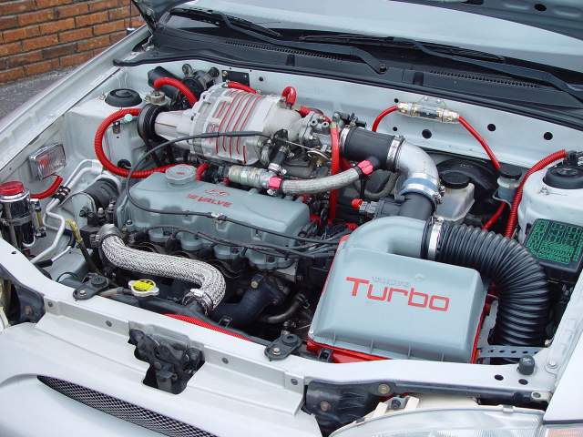
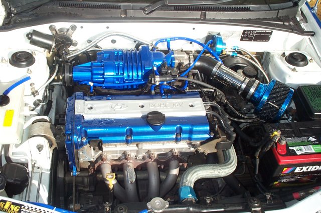
Most blown motors dont have any sort of plenum thou...and this is the most efficient way to do it. Ie the big V8's - the blower sits straight ontop of the motor, blowing directly into the chambers in the heads (sometimes using a very short manifold)

Other types of setups on small cars have had the blower mounted externally & having the blower outlet plumbed directly into the throttle body.
Posted: Fri Nov 03, 2006 7:09 pm
by bigpitty1
Can't wait to see it finished, what type of ECU will you be using, stand alone or still sticking to a piggy back type.
Posted: Fri Nov 03, 2006 9:47 pm
by mxysxy
Ben,
I hope when you succesfully finished with this project, you will not tell me I cant copy it, because my engine is Mivec,
Do something that will help us all please