Also this is NOT a job for amatuers... you need a reasonably sound knowledge of mechanics to get this right or you could make things worse.
Tools:
10mm socket
12mm socket
22mm socket
10mm ring spanner
12mm ring spanner
Ratchet with extension bar
philips screw driver
feeler gauges
vice grips
Modified 10mm ring spanner
Step 1:
Remove the 5 x 10mm screws than hold down the engine cover.

Step 2:
remove the leads from the coils and the connectors, then remove the 6 x 10mm bolts that hold down the coils and remove them.

Step 3:
remove the 9 x 10mm bolts that hold down the rocker cover, they sit in a rubber grommit, they don't have to come out all the way.
Also remove the PCV hose and breather hose.

Step4:
remove the 4 x 10mm bolts that hold the timing cove on.

Step5:
you should be able to remove the rocker cover off, it might be abit hard because it might of not been taken off for a couple of years, probably the best way is to give the rocker cover a few taps with a rubber mallet and hold on to the oil cap and pull it off.

Now with the cover off you should be able to see the tappets.

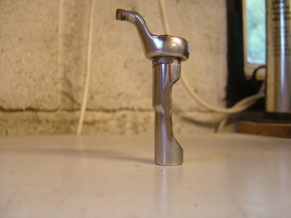
undoing the lock nuts on the tappets can be a bit of a bitch as they sit under the cam, so basically you can't get a socket or a spanner in there, I ended up modifing a 10mm ring spanner, bent it and then got the vice grip to use as a lever.

alright now we are up to the part where you adjust the tappet, the clearance is .10mm for intake and .13mm for exhaust when cold and .16mm intake and .21mm exhaust when engine is hot, I did mine when it was cold.
you get your modified 10mm spanner and loosen the lock nut (don't take it off) in the middle of that nut is a screw, that screw adjusts the clearance.
put the feeler gauge between the rocker and valve, its a bit tricky but it would be easier if you had small hands as you got to get your fingers in there.
Adjust the screw so the feeler gauge fits in the gap nice and snug, it shouldn't be too tight or too loose, you should be able to move it around in the gap with a bit of resistance, then you tighten up the lock nut and then recheck the clearance.
remember that the cam lobe should be facing up so it is not puching the valve open, get the 22mm socket and ratchet on the crank so you can rotate the engine.
in the pic I got the spanner, screw driver and feeler gauges in there at the same time, you will work a rythm of getting them done.

basically that is it one down and 23 to go, also when putting the rocker cover back on you don't really have to tighten the bolts up real tight, only nip them up, its a rubber gasket make sure it seals probably or it will leak,
thats basially th front, the rear it the same but you have to remove the intake manifold.